
When engineers compare nickel-plated carbon fiber tow, a common question is whether more nickel always means lower resistance. Within the same product family, higher nickel content often corresponds to lower longitudinal tow resistance. That trend is meaningful when the base fiber, tow size, coating route and resistance test conditions are comparable.
Our recommendation is to start with the target resistance and an acceptable weight per unit length, then compare suitable nickel levels. A move to a higher-nickel grade should deliver a verified benefit in the intended design. Coating continuity, electrical contacts, processing requirements and the intended electrical function all belong in that decision.
Why Nickel Content Matters
A nickel layer can provide a more conductive path along the carbon fiber surface. Increasing the deposited nickel within one controlled product series may change several properties at the same time:
- Longitudinal tow resistance
- Finished coated tow linear density
- Metal weight per unit length
- Flexibility and handling
- Processing window and quotation requirements
The final electrical result also depends on coating coverage, thickness distribution, porosity or discontinuities, and the electrical contacts used in testing. We treat nickel loading as a design trade-off between resistance, weight and processability, and compare those properties together.
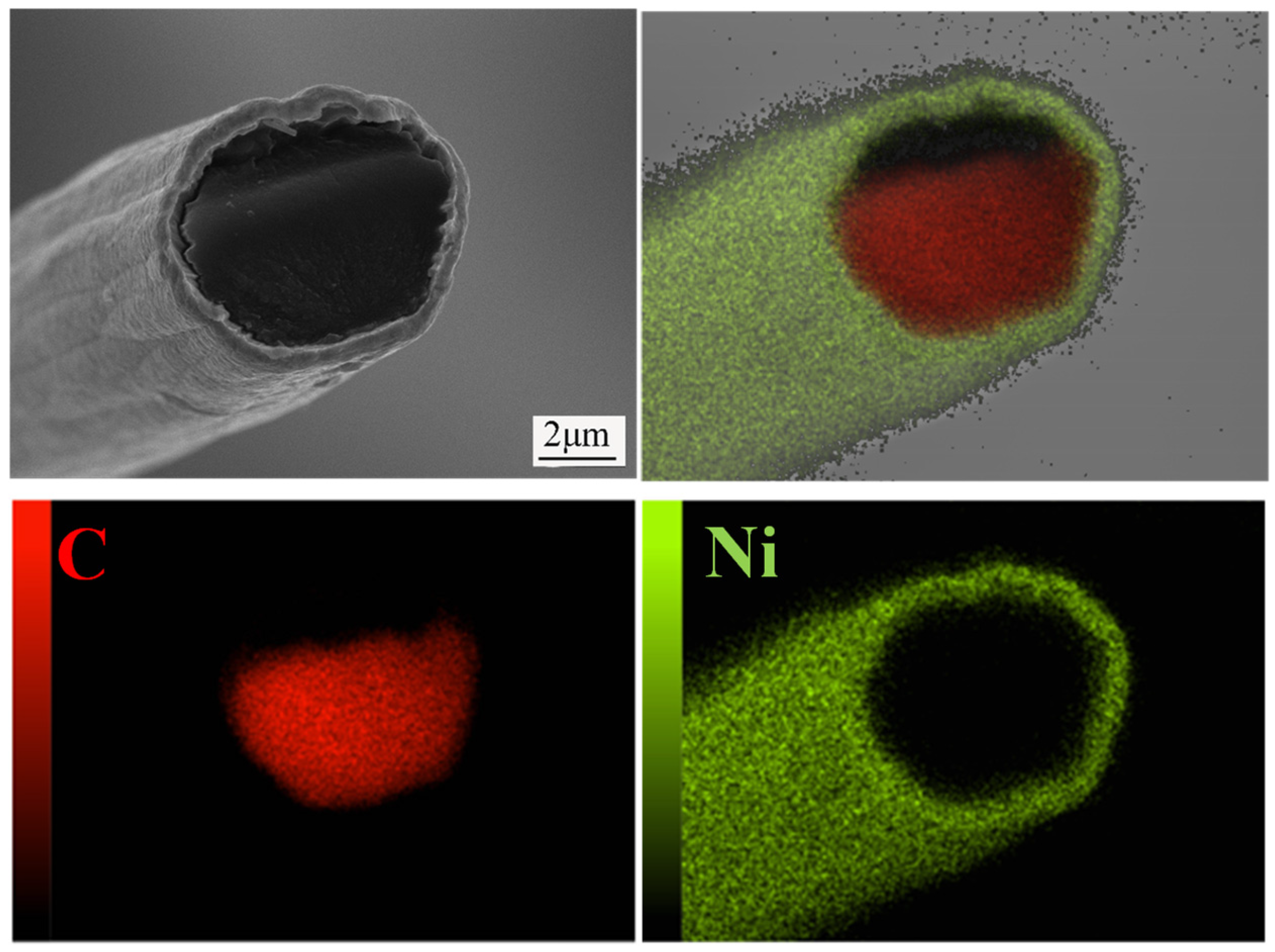
Nickel wt% alone does not identify the deposition route. For process verification or a material substitution review, see our comparison of CVD and electroplated nickel-coated carbon fiber.
Comparing Nickel Content and Resistance
Before comparing grades, control or disclose the following variables so that a nickel-content trend can be interpreted meaningfully.
| Comparison item | Why it matters |
|---|---|
| Base-fiber grade | Different base fibers can have different filament properties and linear densities. |
| Tow size | 3K, 12K and 24K differ in filament count and finished linear density. |
| Coating route and conditions | Nickel wt% alone does not establish coating distribution or continuity. |
| Nickel-content basis | Use the same denominator; this article uses the mass of the finished coated fiber. |
| Resistance test method | Gauge length, contacts, tension, temperature and conditioning can affect the measured value. |
When comparing 3K, 12K or 24K tows, we first confirm the exact base-fiber designation, tow size and deposition route. The same nickel wt% can correspond to different conductive cross-sections and coating conditions. Supplier data measured under different conditions should not be ranked as if the results were directly interchangeable.
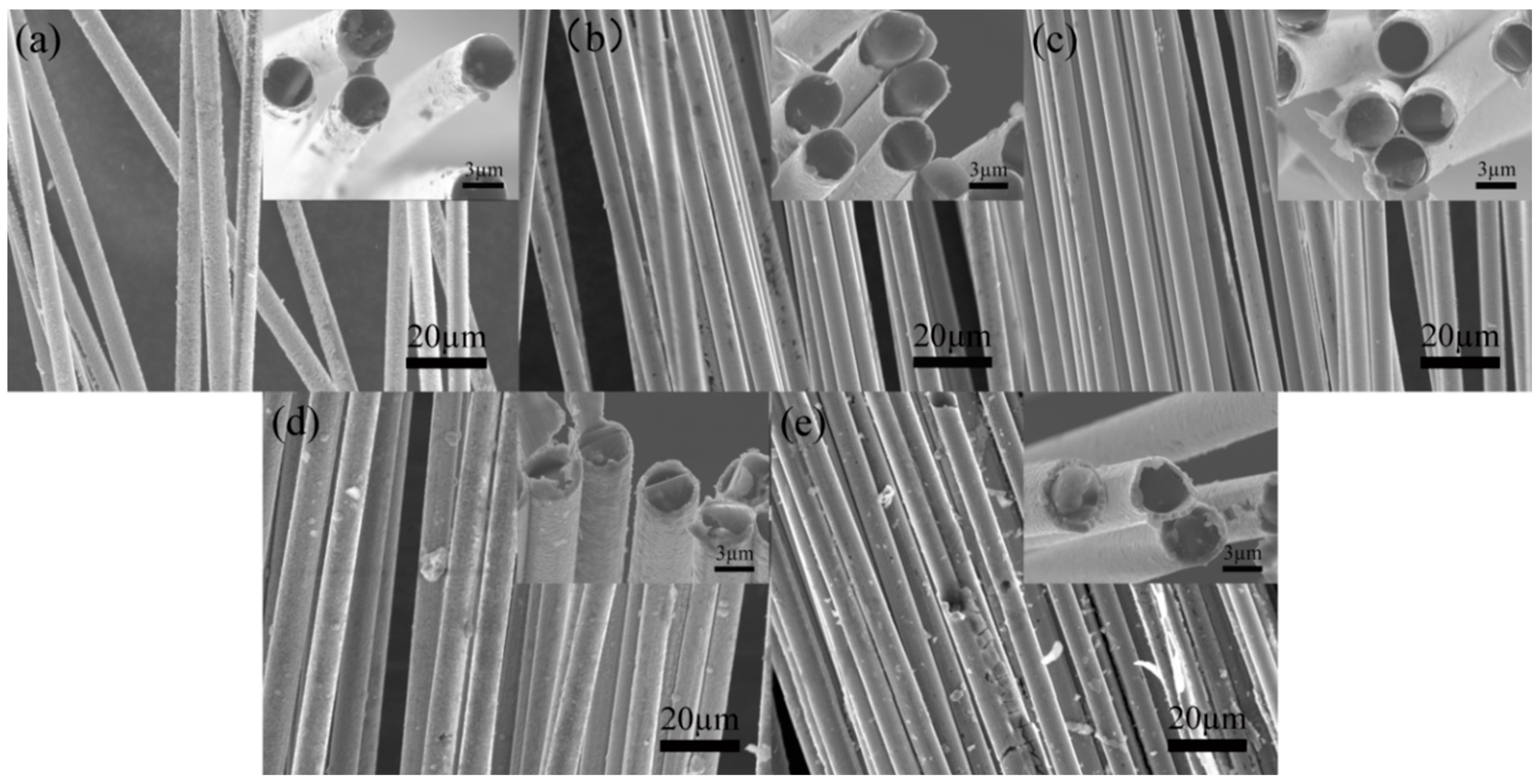
Nickel Content and Finished Tow Linear Density
The nickel layer adds weight as well as a conductive path. A simple mass balance helps explain how nickel content affects the calculated linear density of a coated tow:
Finished tow linear density = uncoated base-tow linear density ÷ (1 − nickel mass fraction)
The nickel mass fraction is the nickel share of the finished coated-tow mass, expressed as a decimal.
This relationship assumes that the non-nickel mass per unit length remains essentially unchanged. The base-tow value and nickel percentage need a consistent sizing and moisture basis. If original sizing is removed or additional sizing is applied, those mass changes need to be accounted for.
The result is a calculated mass per unit length, not a measured batch value. It cannot predict longitudinal resistance. Coating continuity, thickness distribution and electrical contacts can produce different resistance results at similar nickel contents.
For grade selection, we therefore compare nickel content, finished linear density and measured resistance together. A higher nickel percentage deserves a process trial against the resistance target, weight limit and handling requirements of the intended design.
Compare Resistance Under the Same Test Conditions
When comparing Ω/m values, we ask for both the test method and the reporting basis: DC or AC measurement, two-wire or four-wire configuration, gauge length, contact locations and pressure, tow tension, temperature and conditioning, specimen count, and how the result is summarized.
The test current should avoid appreciable self-heating. For AC measurements, state the frequency and distinguish resistance from impedance. Four-wire measurement can reduce lead and other added resistance contributions, but tow contacts and voltage-sensing locations still need to be defined.
Using 50–55 wt% as a Starting Point
A 50–55 wt% range is common in Saxobran’s current supply information and can be a starting point for comparison. Our recommendation is to choose the nickel level against the required resistance, weight limit and processing conditions. A higher-nickel option should demonstrate the performance benefit needed to justify its added weight. The following questions help structure that comparison:
| Design question | What to evaluate |
|---|---|
| Is a lower Ω/m value required | Compare grades within the same series and method, and confirm whether the reduction meets the design requirement. |
| Is weight per unit length limited | Compare finished linear density with measured resistance. |
| Will the tow be bent, braided or over-extruded | Evaluate handling, bending conditions, coating retention, contact design and resistance after processing. |
| Is the material used in a composite | Test the actual resin, fiber loading, dispersion or layup; source-tow Ω/m does not replace finished-part resistivity. |
| Is a narrow electrical window specified | Agree on sampling, test method, tolerance and acceptance criteria before quotation. |
Understanding Longitudinal Tow Resistance
For continuous tow, Ω/m describes longitudinal resistance per unit length under stated measurement conditions. It is not the same as volume resistivity in Ω·m or Ω·cm, electrical conductivity in S/m, surface resistance, or the resistance of a finished cable or assembly.
The tow’s Ω/m value also does not by itself establish:
- EMI shielding effectiveness of a finished composite
- Safe continuous-current, fault-current or lightning-current capability
- Heating temperature and thermal uniformity
- Flex life, termination durability or environmental stability
- Final compound or molded-part resistivity
Those results also depend on the final structure, contacts, insulation, resin or matrix system, fiber loading, geometry, environment and test method. We recommend using tow data to shortlist grades, then confirming suitability through the actual process and finished-part tests.
Information to Provide Before Grade Selection
For a useful technical comparison, we suggest providing:
- Required tow size and exact base-fiber designation
- Target longitudinal resistance range and required test method
- Nickel-content requirement and percentage basis, if specified
- Maximum finished linear density or weight limit, if applicable
- Processing route, such as braiding, over-extrusion, compounding or layup
- Intended electrical function and final validation plan
- Sample length, packaging and quantity
Common Grade Selection Questions
Why Equal Nickel Content Can Give Different Resistance
The same nickel content does not establish the same base fiber, tow size or coating continuity. We first check those conditions, then compare Ω/m results obtained using the same method.
What to Request with a Resistance Value
We recommend requesting the exact grade, test conditions, specimen count and reporting basis alongside the resistance value. That information helps determine whether it can be compared with the project’s target range.
Request Grade Specific Data
If you are comparing nickel-plated carbon fiber tow grades, share your tow size, nickel-content basis, target Ω/m range, weight limit, test method and processing requirements. We can use those requirements to check available grade-specific information and sample options for engineering evaluation. For supply forms and technical data, see our nickel-plated carbon fiber product page.
